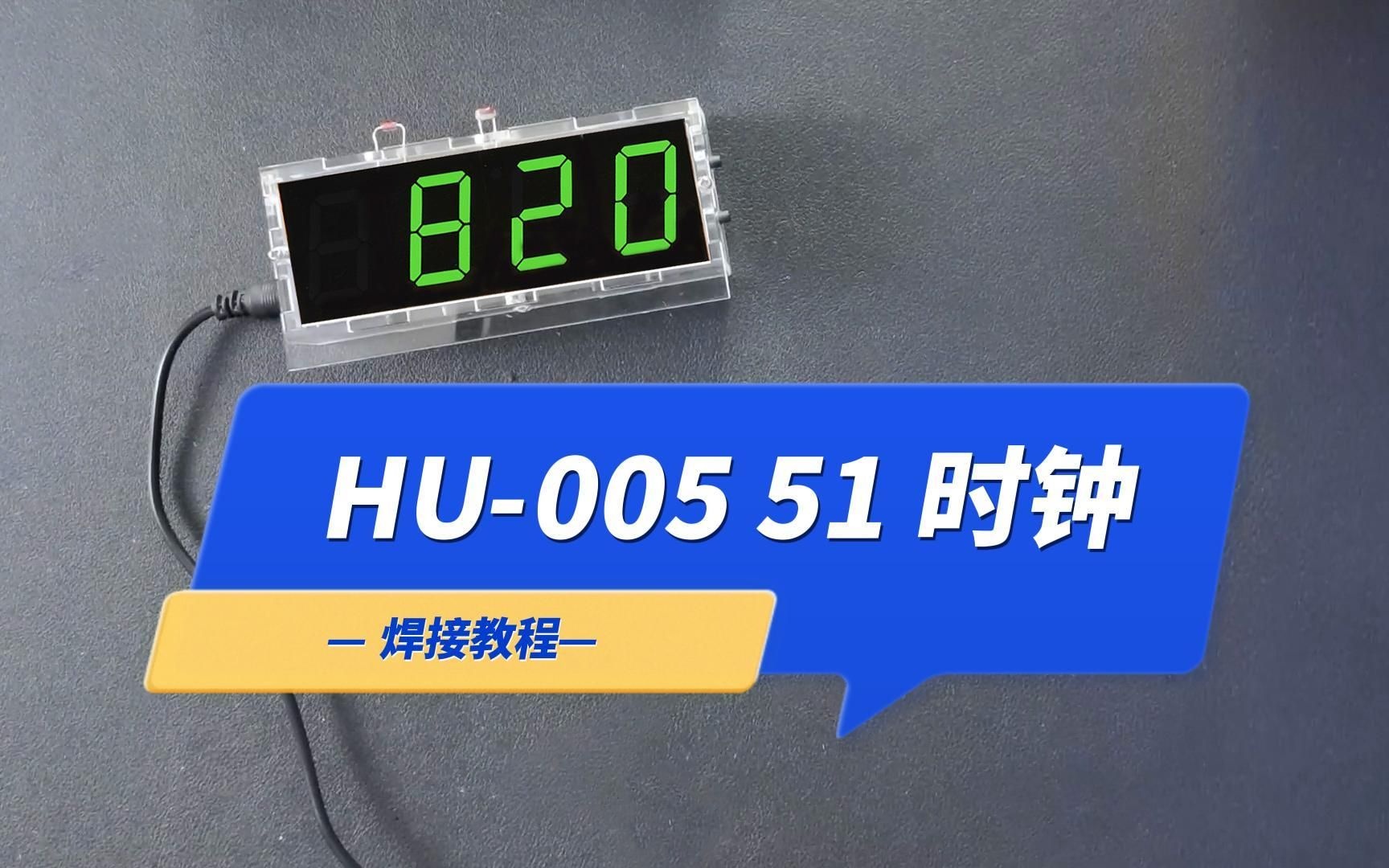
HU-005 51单片机时钟制作套件 51 single chip clock making kit
☞关注公众号再阅读!☜
☞防止下次再迷路!!☜
1.产品焊接组装成果展示图
Product welding assembly results

2.元件清单
Component list


3.元件分布图
Component distribution diagram

4.电路原理图
Schematic

5.焊接方法
Welding method

6.电路板焊接步骤细节
PCB Welding procedure details
1.焊接330Ω、10K电阻(无极性)。
Welding 330Ω, 10K resistance (no polarity).


2.焊接圆柱晶振、22PF和104瓷片电容(三者均无极性),如下图所示。
Welded cylindrical crystal, 22PF and 104 ceramic capacitors (all of which have no polarity), as shown in the figure below.


3.按丝印图形放置焊接,如下图所示。
Place the soldering according to the silk screen pattern, as shown in the figure below.


4.焊接光敏电阻、热敏电阻,如下图所示。
Solder the photoresistor and thermistor as shown below.

5.焊接28P-IC座、8P-IC座(U形缺口对应丝印图形),如下图所示。
Welding 28P-IC seat, 8P-IC seat (U-shaped notch corresponds to the silk screen graphics), as shown below.

6.对应丝印图形放置、焊接S8550三极管,如下图所示。
Corresponding to the placement and soldering of the S8550 triode, as shown in the figure below.

7.焊接侧按键开关,如下图所示。
The key switch on the welding side is shown below.

8.焊接蜂鸣器(引脚:长+短-),如下图所示。
Welding buzzer (pin: long + short-), as shown below.


9.焊接电源插座(DC5V供电),如下图所示。
Welding power socket (DC5V power supply), as shown below.

10.焊接1位1寸数码管(第三位数码管倒置),如下图所示。
Weld a 1-inch digital tube (the third digital tube is upside down) as shown in the figure below.


11.将滤光膜贴在数码管上,剪掉多余的部分。
Attach the filter film to the digital tube and cut off the excess.


12.将纽扣电池+极朝上放入电池扣,如下图所示。
Put the button battery + pole up into the battery button, as shown in the figure below.

13.最后,将芯片引脚稍向内弯折,放入对应的IC座(注意U形缺口方向与丝印图案一致)。
Finally, bend the chip pins slightly inwards and put them into the corresponding IC holder (note that the direction of the U-shaped notch is consistent with the silkscreen pattern).


7.外壳安装说明
Shell installation instructions
1.撕掉亚克力外壳两面的保护膜。
Attach the filter film to the digital tube and cut off the excess.

2.如下图所示,安装左右两侧面外壳(对应开口位置)。
As shown in the figure below, install the left and right side shells (corresponding to the opening position).


3.安装上下面外壳,顶板注意对应传感器开口位置。
Install the lower case, pay attention to the position of the sensor opening on the top plate.


4.最后安装背面外壳,注意蜂鸣器开孔对应,如下图所示。
Finally, install the back shell, pay attention to the corresponding opening of the buzzer, as shown below.

用螺丝螺母固定对应位置,如下图所示。
Fix the corresponding position with screw nuts as shown in the figure below.


到此安装完毕。
This is the end of the installation.
结束
The End


