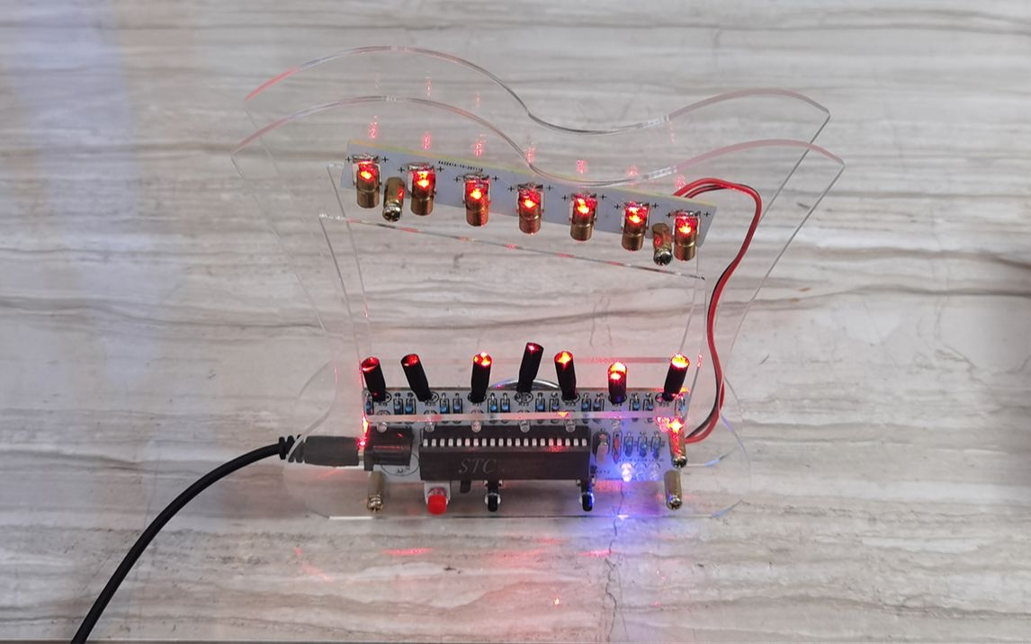
HU-013 激光竖琴制作套件Laser Harp Making Kit
1.产品焊接组装成果展示图
Product welding assembly results


L:低音 M:中音 H:高音
L: Bass M: Midrange H: Treble
DC5V供电
2.元件清单
Component list


3.元件分布图
Component distribution diagram


4.电路原理图
Schematic


5.焊接方法
Welding method

6.电路板焊接步骤细节
PCB Welding procedure details
1.焊接510、1K、10K直插电阻(无极性),阻值对应电路板上的丝印标识焊接,如下图所示。
Solder510、 1K, 10K in-line resistance (no polarity), the resistance value corresponds to the silk-screen logo welding on the circuit board, as shown in the figure below.


2.焊接12Mhz晶振、22PF瓷片电容,如下图所示。
Solder 12Mhz crystal and 22PF ceramic capacitors, as shown in the figure below.

3.将10uF电解电容放倒后焊接,引脚:长+短-(白色条纹阴影为负极),如下图所示。
Put the 10uF electrolytic capacitor upside down and solder it, the pin: long + short-(the white stripe shade is the negative electrode), as shown in the figure below.

4.焊接IC芯片座,U形缺口对应丝印图案,如下图所示。
Soldering the IC chip holder, the U-shaped notch corresponds to the silk screen pattern, as shown in the figure below.

5.焊接LED发光二极管,引脚:长正+短﹣,如下图所示。
Weld the LED light-emitting diode, the pin: long positive + short -, as shown in the figure below.


6.焊接光敏电阻(无极性),引脚留约1cm长,以便套热缩管,如下图所示。
Solder the photoresistor (no polarity), and leave the pins about 1cm long to fit the heat shrink tube, as shown in the figure below.


7.焊接S8550三极管,注意对应丝印图案放置,如下图所示。
Solder the S8550 transistor, pay attention to the placement of the corresponding silk screen pattern, as shown in the figure below.


8.焊接DC5V电源端子,如下图所示。
Solder the DC5V power terminal as shown in the figure below.

9.焊接自锁开关,如下图所示。
Weld the self-locking switch, as shown in the figure below.

10.焊接直插按键开关,如下图所示。
Weld the push button switch, as shown in the figure below.


11.裁剪热缩管每段约1cm,将其套入光敏电阻,如下图所示。
Cut each section of the heat shrinkable tube to about 1cm, and put it into the photoresistor, as shown in the figure below.


然后用电烙铁烫收紧热缩管下端,如下图所示。
Then tighten the lower end of the heat shrinkable tube with an electric soldering iron, as shown in the figure below.


12.将喇叭线焊接至喇叭,注意对应极性,红色+黑色﹣。
Solder the speaker wire to the speaker, pay attention to the corresponding polarity, red + black -.

对应正负极焊接到电路板上,如下图所示。
The corresponding positive and negative poles are soldered to the circuit board, as shown in the figure below.

用双面胶将喇叭固定到电路板背面,如下图所示。
Fix the speaker to the back of the circuit board with double-sided tape, as shown in the figure below.


13.适当剪短激光发射器引脚,红线+蓝线-,如下图所示。
Properly cut the laser emitter pins, red wire + blue wire -, as shown in the figure below.


将激光头发射器焊接至电路板,注意记性,如下图所示。
Solder the laser head transmitter to the circuit board, pay attention to the memory, as shown in the figure below.


调整激光发射器尽可能在一水平线,使光路准直出射,如下图所示。
Adjust the laser transmitter as much as possible to a horizontal line, so that the light path is collimated, as shown in the figure below.

14.焊接红黑线连接两块电路板,红+黑-,如下图所示。
Solder the red and black wires to connect the two circuit boards, red + black -, as shown in the figure below.

15.如下图所示,将芯片引脚稍向内掰折,以便安装。
As shown in the figure below, fold the chip pins slightly inward for easy installation.


芯片U形缺口对应丝印图案放着,如下图所示。
The U-shaped notch of the chip is placed corresponding to the silk screen pattern, as shown in the figure below.


7.外壳安装说明
Shell installation instructions
1.撕掉外壳两面的保护膜,如下图所示。
Tear off the protective film on both sides of the housing, as shown in the figure below.


2.将螺丝、单通铜柱固定在底面板上,如下图所示。
Fix the screws and single-pass copper pillars on the bottom panel, as shown in the figure below.


3.安装电路板,并用双通铜柱锁紧固定,如下图所示。
Install the circuit board and lock it with a double-pass copper column, as shown in the figure below.

4.DC5V供电后,开启电源开关,调整光敏电阻位置,确保激光照射在光敏电阻上,如下图所示。
After DC5V power supply, turn on the power switch and adjust the position of the photoresistor to ensure that the laser is irradiated on the photoresistor, as shown in the figure below.

最后用螺丝固定安装顶面板,如下图所示。
Finally, fix and install the top panel with screws, as shown in the figure below.


到此安装完毕。
This is the end of the installation.
结束
The End


