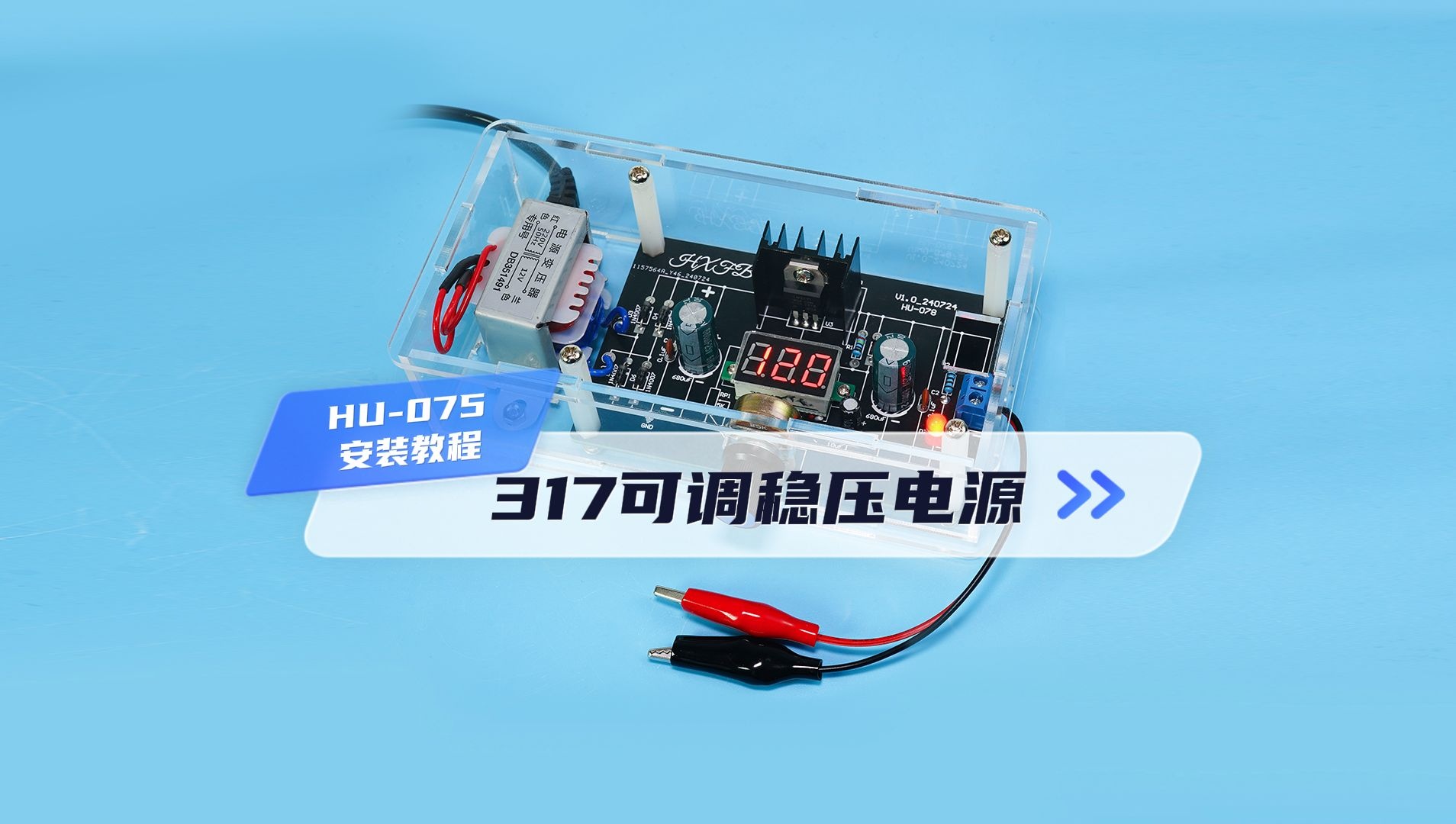
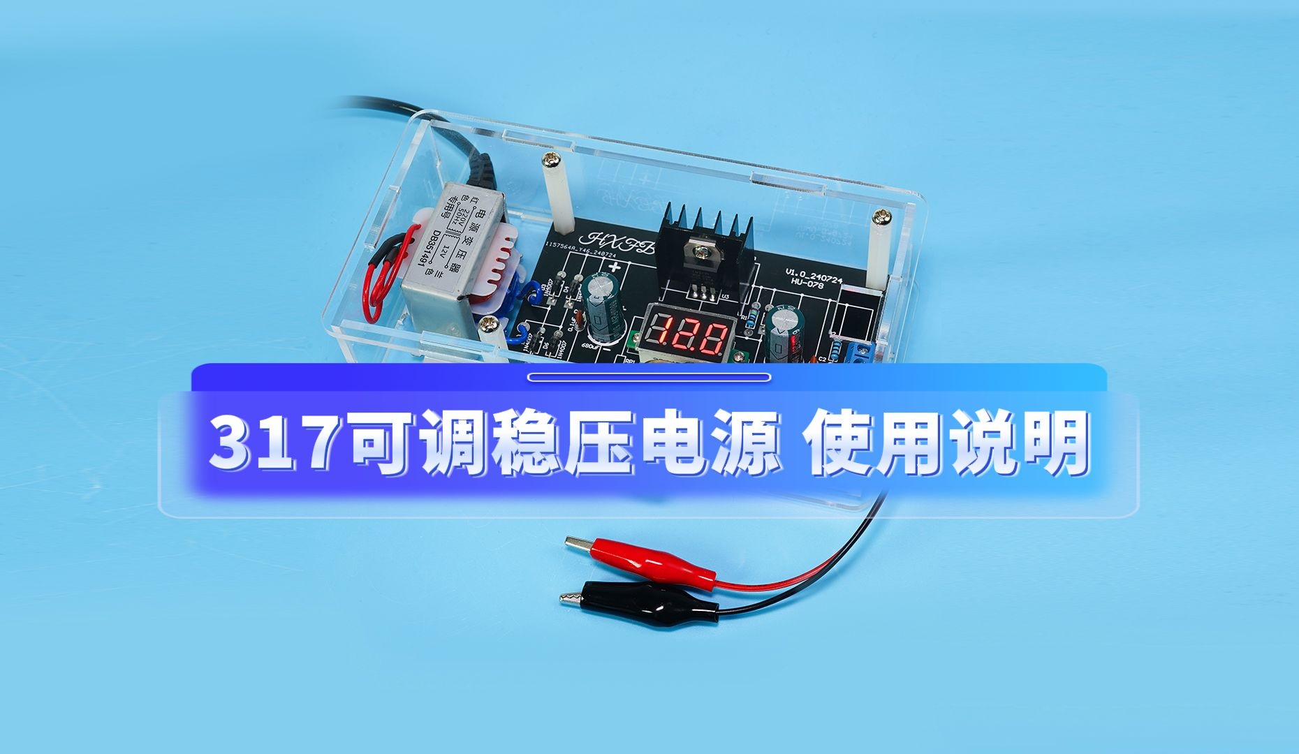
HU-078 317可调稳压电源
安装视频

使用说明

HU-078 317可调稳压电源
317 adjustable voltage regulator power supply
Ⅰ、功能 Function
1、输入交流经过整流和稳压输出直流
Input AC is rectified and stabilized to output DC
2、电位器调节输出电压
Potentiometer adjusts output voltage
3、电压表显示输出电压
The voltmeter displays the output voltage
Ⅱ、特性 Characteristic
1、电路板丝印印有电路图,更加直观理解电路原理
Printed circuit boards with silk screen printing of circuit diagrams provide a more intuitive understanding of circuit principles
2、电源功率:2W
Power supply: 2W
3、PCB尺寸:98mm*62mm
PCB size: 98mm * 62mm
4、输出电压:约1.25-12V
Output voltage: approximately 1.25-12V
5、最大电流:输出电压5V时,电流约200mA
Maximum current: When the output voltage is 5V, the current is about 200mA
Ⅲ、元件清单 BOM
|
序号/ Number |
名称 | Name |
标号 /Lable |
数量/ Number |
备注/ Remarks |
| 1 | 1N4007二极管 | 1N4007 diode | D3、D4、D5、D6 | 4 | |
| 2 | 电解电容680uF | Electrolytic capacitor 680uF | C1、C4 | 2 | |
| 3 | 电解电容10uF | Electrolytic capacitor 10uF | C5 | 1 | |
| 4 | LM317芯片 | LM317芯片 | U1 | 1 | |
| 5 | 1N4148二极管 | 1N4148 diode | D1、D2 | 2 | |
| 6 | 瓷片电容104 | Ceramic capacitor 104 | C2、C3 | 2 | |
| 7 | 电位器 | Potentiometer | RP1 | 1 | |
| 8 | 电位器旋钮帽 | Potentiometer knob cap | \ | 1 | |
| 9 | 直插电阻240Ω | Direct insertion resistor 240Ω | R1 | 1 | |
| 10 | 直插电阻1K | Direct insertion resistor 1K | R2 | 1 | |
| 11 | 红色发光二极管 | Red led | D7 | 1 | |
| 12 | 接线端子 | Connecting terminal | P1 | 1 | |
| 13 | 红黑连接线 | Red black connecting wire | \ | 1 | |
| 14 | 热缩管 | Heat Shrink Tubing | \ | 1 | |
| 15 | 电压表 | Voltmeter | U2 | 1 | |
| 16 | 散热片 | Radiator | U1 | 1 | |
| 17 | 黑色鳄鱼夹 | Black crocodile clip | \ | 1 | |
| 18 | 红色鳄鱼夹 | Red crocodile clip | \ | 1 | |
| 19 | 电源线 | Power line | \ | 1 | |
| 20 | 变压器 | Transformer | \ | 1 | |
| 21 | 电路板 | PCB | \ | 1 | |
| 22 | 说明书 | Instructions | \ | 1 | |
| 23 | 亚克力外壳 | Acrylic shell | \ | 1 | 选配 |
Ⅳ、电路原理 Schematic

Ⅴ、元件分布图Component map

Ⅵ、焊接教程 Welding tutorial
1、焊接1N4148二极管。(注意正负极)
Solder 1N4148 diode.(Pay attention to the positive and negative poles)

2、焊接240Ω和1K电阻。
Solder 240 Ω and 1K resistors.

3、焊接1N4007二极管。(注意正负极)
Solder 1N4007 diode.(Pay attention to the positive and negative poles)

4、焊接104瓷片电容。
Solder 104 ceramic capacitors.

5、焊接红色发光二极管。(管脚长+短-)
Solder the red light-emitting diode. (Pin length+ short-)

6、焊接接线端子。
Solder wiring terminals.

7、将电压表线穿过电路板,用M2螺丝和螺母固定电压表。
Thread the voltmeter wire through the circuit board and secure the voltmeter with M2 screws and nuts.

8、在电路板背面焊接电压表线。(VCC接红线,GND接黑线,Vo接白线)
Solder the voltmeter wire on the back of the circuit board. (VCC connected to red wire, GND connected to black wire, Vo connected to white wire)

9、焊接10uF电解电容。(管脚长+短-)
Solder 10uF electrolytic capacitors. (Pin length+short -)

10、焊接电位器。
Solder potentiometer.

11、焊接680uF电解电容。(管脚长+短-)
Solder 680uF electrolytic capacitor. (Pin length+short -)

12、用M3螺丝将LM317固定到散热片上,并焊接。
Fix LM317 onto the heat sink with M3 screws and weld it.

13、将热缩管套到变压器红色线上并和电源线焊接,加热热缩管进行固定。
Insert the heat shrink tubing onto the red wire of the transformer and weld it to the power cord. Heat the heat shrink tubing and secure it in place.

14、将变压器蓝色线焊接到电路板上。
Solder the blue wire of the transformer onto the circuit board.

15、用M3单通铜柱和尼龙柱固定电路板。
Fix the circuit board with M3 single copper and nylon pillars.

16、用M3螺丝和螺母将电路板和变压器固定到底部外壳上。
Secure the circuit board and transformer to the bottom casing using M3 screws and nuts.

17、将电源线固定到外壳上,装好外壳并用M3螺丝固定。
Secure the power cord to the casing, install the casing and fix it with M3 screws.

18、用垫片和螺母将电位器固定到外壳上,并装上旋钮帽。
Secure the potentiometer to the housing with washers and nuts, and install the knob cap.

19、将鳄鱼夹胶套脱下,穿进对应颜色的连接线中,并将线焊到鳄鱼夹上。
Remove the crocodile clip cover, thread it into the corresponding colored connecting wire, and solder the wire onto the crocodile clip.

20、套上鳄鱼夹胶套,并将鳄鱼夹装在接线端子上。(红+黑-)
Put on the crocodile clip and clamp the crocodile onto the terminal block. (Red+Black -)

Ⅶ、使用说明 Instructions for use

注意:散热片一定要和芯片贴紧,否则可能导致LM317芯片过热,电源无法稳定工作!!!
Attention: The heat sink must be tightly attached to the chip, otherwise it may cause the LM317 chip to overheat and the power supply to not work stably!!!


